
GAS CUTTING
GAS CUTTING
The common methods used in cutting metal are oxygas flame cutting, air carbon-arc cutting, and
plasma-arc cutting. The method used depends on the type of metal to be cut and the availability of equipment. As a Steelworker, oxygas or air carbon-arc equipment is the most common type of equipment available for your use. Oxygas equipment is explained in this chapter and air carbon-arc cutting is covered in chapter 7. The oxygas cutting torch has many uses in steelwork. At most naval activities, the Steelworker finds the cutting torch an excellent tool for cutting ferrous metals. This versatile tool is used for operations, such as beveling plate, cutting and beveling pipe, piercing holes in steel plate, and cutting wire rope. When using the oxygas cutting process, you heat a spot on the metal to the kindling or ignition temperature (between 1400°F and 1600°F for steels). The term for this oxygas flame is the PREHEATING FLAME. Next, you direct a jet of pure oxygen at the heated metal by pressing a lever on the cutting torch. The oxygen causes a chemical reaction known as OXIDATION to take place
rapidly. When oxidation occurs rapidly, it is called COMBUSTION or BURNING. When it occurs slowly,
it is known as RUSTING. When you use the oxygas torch method to cut metal,the oxidation of the metal is extremely rapid and part ofthe metal actually burns. The heat, liberated by theburning of the iron or steel, melts the iron oxide formedby the chemical reaction and accelerates the preheatingof the object you are cutting. The molten material runsoff as slag, exposing more iron or steel to the oxygen jet. In oxygas cutting, only that portion of the metal thatis in the direct path of the oxygen jet is oxidized. The narrow slit, formed in the metal as the cutting progresses,is called the kerf. Most of the material removed from the kerf is in the form of oxides (products of the oxidation reaction). The remainder of the material is molten metal that is blown or washed out of the kerf bythe force of the oxygen jet. The walls of the kerf formed by oxygas cutting of ferrous metals should be fairly smooth and parallel to each other. After developing your skills in handling the torch, you can keep the cut within close tolerances; guide the cut along straight, curved, or irregular lines; and cut bevels or other shapes that require holding the torch at an angle. Partial oxidation of the metal is a vital part of the oxygas cutting process. Because of this, metals that do not oxidize readily are not suitable for oxygas cutting. Carbon steels are easily cut by the oxygas process, but special techniques (described later in this chapter) are required for the cutting of many other metals.
OXYGAS CUTTING EQUIPMENT
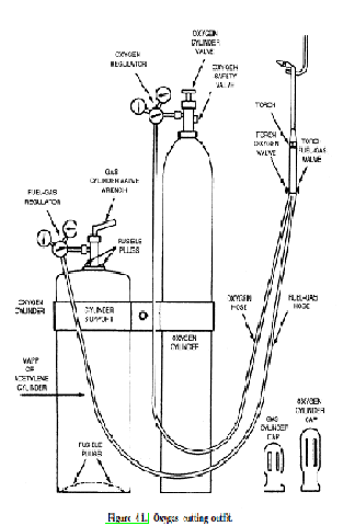
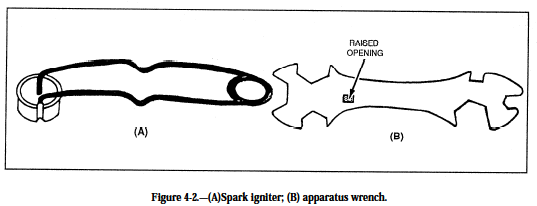
An oxygas cutting outfit usually consists of a cylinder of acetylene or MAPP gas, a cylinder of oxygen, two regulators, two lengths of hose with fittings, and a cutting torch with tips (fig. 4-1). An oxygas cutting outfit also is referred to as a cutting rig. In addition to the basic equipment mentioned above, numerous types of auxiliary equipment are used in oxygas cutting. An important item is the spark igniter that is used to light the torch (fig. 4-2, view A). Another item you use is an apparatus wrench. It is similar in design to the one shown in figure 4-2, view B. The apparatus wrench is sometimes called a gang wrench because it fits all the connections on the cutting rig. Note that the wrench shown has a raised opening in the handle that serves as an acetylene tank key. Other common accessories include tip cleaners, cylinder trucks, clamps, and holding jigs. Personal safety apparel, such as goggles, hand shields, gloves, leather aprons, sleeves, and leggings, are essential and should be worn as required for the job at hand. Information on
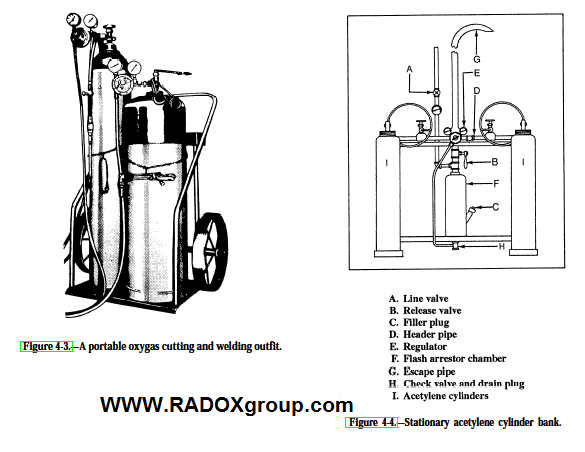
safety apparel is also contained in chapter 3 of this text. Oxygas cutting equipment can be stationary or portable. A portable oxygas outfit, such as the one shown in figure 4-3, is an advantage when it is necessary to move the equipment from one job to another. To conduct your cutting requirements, you must be able to set up the cutting equipment and make the required adjustments needed to perform the cutting operation. For this reason it is important you understand the purpose and function of the basic pieces of equipment that make up the cutting outfit. But, before discussing the equipment, let’s look at the gases most often used in cutting: acetylene, MAPP gas, and oxygen possibility of a regulator exploding if the cylinder valve is opened rapidly.
WARNING
Oil or other petroleum products must never be used around oxygen regulators because these products will either cause a regulator explosion or fire.
HOSES
The hoses used to make the connections between the torch and the regulators must be strong, nonporous, light, and flexible enough to make torch movements easy. They must be made to withstand internal pressures that can reach as high as 100 psig. The rubber used in hose manufacture is specially treated to remove the sulfur that could cause spontaneous combustion. Welding hose is available in single- and double hose lengths. Size is determined by the inside diameter, and the proper size to use depends on the type of work for which it is intended. Hose used for light work has a 3/1 6 or 1/4 inch inside diameter and one or two plies of fabric. For heavy-duty welding and cutting operations, use a hose with an inside diameter of 5/1 6 inch and three to five plies of fabric. Single hose is available in the standard sizes as well as 1/2-, 3/4-, and 1-inch sizes. These larger sizes are for heavy-duty heating and for use
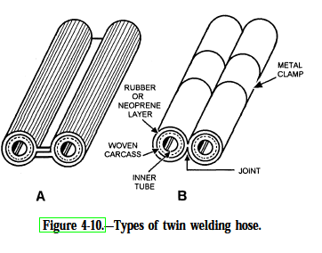
on large cutting machines. The most common type of cutting and welding hose is the twin or double hose that consists of the fuel hose and the oxygen hose joined together side by side. They are joined together by either a special rib (fig. 4-10, view A) or by clamps (fig. 4-10, view B). Because they are joined together, the hoses are less likely to become tangled and are easier to move from place. The length of hose you use is important. The delivery pressure at the torch varies with the length of the hose. A 20-foot, 3/16-inch hose maybe adequate for a job, but if the same hose was 50 feet long, the pressure drop would result in insufficient gas flow to the torch. Longer hoses require larger inside diameters to ensure the correct flow of gas to the torch. When you are having problems welding or cutting, this is one area to check The hoses used for fuel gas and oxygen are identical in construction, but they differ in color. The oxygen hose cover is GREEN, and the fuel-gas hose cover is RED. This color coding aids in the prevention of mishaps thatcould lead to dangerous accidents.
ACETYLENE
Acetylene is a flammable fuel gas composed of carbon and hydrogen having the chemical formula C2H2.Whenburned with oxygen, acetylene produces a hot flame, having a temperature between 5700°F and
6300°F. Acetylene is a colorless gas, having a disagreeable odor that is readily detected even when the gas is highly diluted with air. When a portable welding outfit, similar to the one shown in figure 4-3 is used, acetylene
is obtained directly from the cylinder. In the case of stationary equipment, similar to the acetylene cylinder bank shown in figure 4-4, the acetylene can be piped to a number of individual cutting stations.
Hazards
Pure acetylene is self-explosive if stored in the free state under a pressure of 29.4 pounds per square inch
(psi). A slight shock is likely to cause it to explode.
WARNING
Acetylene becomes extremely dangerous if used above 15 pounds pressure.
Figure 4-4.—Stationary acetylene cylinder bank.
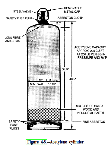
Cylinder Design
Acetylene can be safely compressed up to 275 psi when dissolved in acetone and stored in specially designed
cylinders filled with porous material, such as balsa wood, charcoal, finely shredded asbestos, corn pith, portland cement, or infusorial earth. These porous filler materials aid in the prevention of high-pressure gas
pockets forming in the cylinder. Acetone is a liquid chemical that dissolves large portions of acetylene under pressure without changing the nature of the gas. Being a liquid, acetone can be drawn from an acetylene cylinder when it is not upright. You should not store acetylene cylinders on their side, but if they are, you must let the cylinder stand upright for a minimum of 2 hours before using. This allows the acetone to settle to the bottom of the cylinder.
NOTE: Acetone contaminates the hoses, regulators, torch, and disrupts the flame. Acetylene is measured in cubic feet. The most common cylinder sizes are 130-, 290-, and 330-cubic-foot capacity. The standard size cylinder the Navy uses holds 225 cubic feet of acetylene. Just because a cylinder has a 225-cubic-foot capacity does not necessarily mean it has 225 cubic feet of acetylene in it. Because it is dissolved in acetone, you cannot judge how much acetylene is left in a cylinder by gauge pressure. The pressure of the acetylene cylinder will remain fairly constant until most of the gas is consumed. An example of an acetylene cylinder is shown in figure 4-5. These cylinders are equipped with fusible plugs that relieve excess pressure if the cylinder is exposed to undo heat. The standard Navy acetylene cylinder contains 225 cubic feet of acetylene and weighs about 250 pounds. The acetylene cylinder is yellow, and all compressed-gas cylinders are color-coded for identification. More on the color coding of cylinders is covered later in this chapter.
MAPP GAS
MAPP (methylacetylene-propadiene) is an all-purpose industrial fuel having the high-flame temperature
of acetylene but has the handling characteristics of propane. Being a liquid, MAPP is sold by the pound,
rather than by the cubic foot, as with acetylene. One cylinder containing 70 pounds of MAPP gas can accomplish
the work of more than six and one-half 225-cubicfoot acetylene cylinders; therefore, 70 pounds of MAPP gas is equal to 1,500 cubic feet of acetylene.
Cylinder Design
Total weight for a MAPP cylinder, which has the same physical size as a 225-cubic-foot acetylene cylinder, is 120 pounds (70 pounds which is MAPP gas). MAPP cylinders contain only liquid fuel. There is no cylinder packing or acetone to impair fuel withdrawal; therefore, the entire contents of a MAPP cylinder can be used. For heavy-use situations, a MAPP cylinder delivers more than twice as much gas as an acetylene cylinder for the same time period.
MAPP Characteristics
Because of its superior heat transfer characteristics, MAPP produces a flame temperature of 5300°F when
burned with oxygen. MAPP equals, or exceeds, the performance of acetylene for cutting, heating, and brazing. MAPP is not sensitive to shock and is nonflammable in the absence of oxygen. There is no chance of an explosion if a cylinder is bumped, jarred, or dropped. You can store or transport the cylinders in any position with no danger of forming an explosive gas pocket. The characteristic odor, while harmless, gives warnings of fuel leaks in the equipment long before a dangerous condition can occur. MAPP gas is not restricted to a maximum working pressure of 15 psig, as is acetylene. In jobs requiring higher pressures and gas flows, MAPP can be used safely at the full-cylinder pressure of 95 psig at 70°F. Because of this, MAPP is an excellent gas for underwater work.
Bulk MAPP Gas
Bulk MAPP gas facilities, similar to liquid oxygen stations, are installed at some activities where large
supplies of the gas are used. In bulk installations, MAPP gas is delivered through a piping system directly to the
user points. Maximum pressure is controlled centrally for efficiency and economy. Cylinder-filling facilities are also available from bulk installations that allow users to fill their cylinders on site. Filling a 70-pound MAPP cylinder takes one man about 1 minute and is essentially like pumping
water from a large tank to a smaller one.
MAPP Gas Safety
MAPP gas vapor is stable up to 600°F and 1,100 psig when exposed to an 825°F probe. The explosive
limits of MAPP gas are 3.4 percent to 10.8 percent in air or 2.5 percent to 80 percent in oxygen. As shown in figure 4-6, you can see these limits are narrow in comparison with that of acetylene.
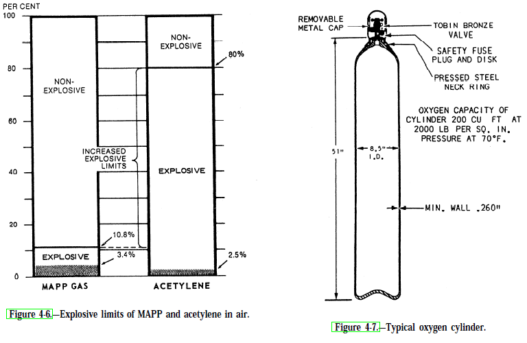
figure 4-6, you can see these limits are narrow in comparison with that of acetylene. MAPP gas has a highly detectable odor. The smell is detectable at 100 ppm, or at a concentration of 1/340th of its lower explosive limit. Small fuel-gas systems may leak 1 or 1 1/2 pounds of fuel or more in an 8-hour shift; bulk systems will leak even more. Fuel-gas leaks are often difficult to find and often go unnoticed; however, a MAPP gas leak is easy to detect and can be repaired before it becomes dangerous. MAPP toxicity is rated “very slight,” but high concentrations
(5,000 ppm) may have an anesthetic effect. Local eye or skin contact with MAPP gas vapor causes no adverse effect; however, the liquid fuel can cause dangerous frostlike burns due to the cooling caused by the rapid evaporation of the liquid. The identification markings on a MAPP cylinder are a yellow body with band “B” colored orange and the top yellow. corrosion of aluminum are all due to the action of atmospheric oxygen. This action is known as oxidation. Oxygen is obtained commercially either by the liquid-air process or by the electrolytic process. In the liquid-air process, the air is compressed and then cooled to a point where the gases become liquid (approximately –375°F). The temperature is then raised to above –321 ‘F, at which point the nitrogen in the air
becomes gas again and is removed. When the temperature of the remaining liquid is raised to –297°F, the
oxygen forms gas and is drawn off. The oxygen is further purified and compressed into cylinders for use.
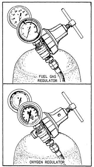
The other process by which oxygen is produced— the electrolytic process—consists of running an electrical current through water to which an acid or an alkali has been added. The oxygen collects at the positive terminal and is drawn off through pipes to a container. Oxygen is supplied for oxyacetylene welding in seamless steel cylinders. A typical oxygen cylinder is shown in figure 4-7. The color of a standard oxygen cylinder used for industrial purposes is solid green. Oxygen cylinders are made in several sizes. The size most often used in welding and cutting is the 244-cubicfoot capacity cylinder. This cylinder is 9 inches in diameter, 51 inches high, and weighs about 145 pounds
and is charged to a pressure of 2,200 psi at 70°F.
OXYGEN
Oxygen is a colorless, tasteless, and odorless gas and is slightly heavier than air. It is nonflammable but supports combustion with other elements. In its free state, oxygen is one of the more common elements. The atmosphere is made up of about 21 parts of oxygen and 78 parts of nitrogen, the remainder being rare gases. Rusting of ferrous metals, discoloration of copper, and You can determine the amount of oxygen in a compressed- gas cylinder by reading the volume scale on the high-pressure gauge attached to the regulator.
REGULATORS
You must be able to reduce the high-pressure gas in a cylinder to a working pressure before you can use it. This pressure reduction is done by a regulator or reducing valve. The one basic job of all regulators is to take the high-pressure gas from the cylinder and reduce it to a level that can be safely used. Not only do they control the pressure but they also control the flow (volume of gas per hour). Regulators come in all sizes and types. Some are designed for high-pressure oxygen cylinders (2,200 psig), while others are designed for low-pressure gases, such as natural gas (5 psig). Some gases like nitrous oxide or carbon dioxide freeze when their pressure is reduced so they require electrically heated regulators. Most regulators have two gauges: one indicates the cylinder pressure when the valve is opened and the other indicates the pressure of the gas coming out of the regulator. You must open the regulator before you get a reading on the second gauge. This is the delivery pressure of the gas, and you must set the pressure that you need for your particular job. The pressures that you read on regulator gauges is called gauge pressure. If you are using pounds per square inch, it should be written as psig (this acronym means pounds per square inch gauge). When the gauge on a cylinder reads zero, this does not mean that the cylinder is empty. In actuality, the cylinder is still full of gas, but the pressure is equal to the surrounding atmospheric pressure. Remember: no gas cylinder is empty unless it has been pumped out by a vacuum pump. There are two types of regulators that control the flow of gas from a cylinder. These are either single-stage or double-stage regulators.
Single-Stage Regulators
Regulators are used on both high- and low-pressure systems. Figure 4-8 shows two SINGLE-STAGE regulators: one for acetylene and one for oxygen. The regulator mechanism consists of a nozzle through which the gases pass, a valve seat to close off the nozzle, a diaphragm, and balancing springs. These mechanisms are all enclosed in a suitable housing. Fuel-gas regulators and oxygen regulators are basically the same design. The difference being those designed for fuel gases are
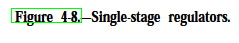
not made to withstand the high pressures that oxygen regulators are subjected to. In the oxygen regulator, the oxygen enters through the high-pressure inlet connection and passes through a glass wool falter that removes dust and dirt. Turning the adjusting screw IN (clockwise) allows the oxygen to pass from the high-pressure chamber to the low-pressure chamber of the regulator, through the regulator outlet, and through the hose to the torch. Turning the adjusting screw further clockwise increases the working pressure; turning it counterclockwise decreases the
working pressure. The high-pressure gauge on an oxygen regulator is graduated from 0 to 3,000 psig and from 0 to 220 in cubic feet. This allows readings of the gauge to determine cylinder pressure and cubic content. Gauges are calibrated to read correctly at 70°F. The working pressure gauge may be graduated in “psig” from 0 to 150,
0 to 200, or from 0 to 400, depending upon the type of regulator used. For example, on regulators designed for
heavy cutting, the working pressure gauge is graduated from 0 to 400. The major disadvantage of single-stage regulators is that the working gas pressure you set will decrease as the cylinder pressure decreases; therefore, you must constantly monitor and reset the regulator if you require a fixed pressure and flow rate. Keeping the gas pressure and flow rate constant is too much to expect from a regulator that has to reduce the pressure of a full cylinder from 2,200 psig to 5 psig. This is where double-stage regulators solve the problem.
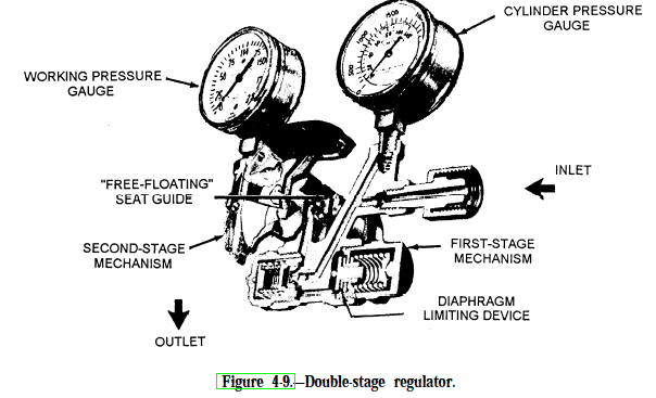
Double-Stage Regulators
The double-stage regulator is similar in principle to the one-stage regulator. The main difference being that
the total pressure drop takes place in two stages instead of one. In the high-pressure stage, the cylinder pressure
is reduced to an intermediate pressure that was predetermined by the manufacturer. In the low-pressure stage, the pressure is again reduced from the intermediate pressure to the working pressure you have chosen. A typical double-stage regulator is shown in figure 4-9.
Problems and Safety
Regulators are precise and complicated pieces of equipment. Carelessness can do more to ruin a regulator than any other gas-using equipment. One can easily damage a regulator by simply forgetting to wipe clean the cylinder, regulator, or hose connections. When you open a high-pressure cylinder, the gas can rush into the regulator at the speed of sound. If there is any dirt present in the connections, it will be blasted into the precision-fitted valve seats, causing them to leak This results in a condition that is known as creep. Creep occurs when you shut of the regulator but not the cylinder and gas pressure is still being delivered to the low-pressure side. Regulators are built with a minimum of two relief devices that protect you and the equipment in the case of regulator creep or high-pressure gas being released into the regulator all at once. All regulator gauges have blow out backs that release the pressure from the back of the gauge before the gauge glass explodes. Nowadays, most manufacturers use shatterproof plastic instead of glass. The regulator body is also protected by safety devices. Blowout disks or spring-loaded relief valves are the two most common types of devices used. When a blowout disk ruptures, it sounds like a cannon. Springloaded relief valves usually make howling or shrieking like noises. In either case, your first action, after you recover from your initial fright, should be to turn off the cylinder valve. Remove the regulator and tag it for repair
or disposal. When opening a gas cylinder, you should just “crack” the valve a little. This should be done before attaching the regulator and every time thereafter. By opening the cylinder before connecting the regulator, you blow out any dirt or other foreign material that might be in the cylinder nozzle. Also, there is the possibility of a regulator exploding if the cylinder valve is opened rapidly.
WARNING
Oil or other petroleum products must never be used around oxygen regulators because these products will either cause a regulator explosion or fire.
HOSES
The hoses used to make the connections between the torch and the regulators must be strong, nonporous, light, and flexible enough to make torch movements easy. They must be made to withstand internal pressures that can reach as high as 100 psig. The rubber used in hose manufacture is specially treated to remove the sulfur that could cause spontaneous combustion. Welding hose is available in single- and double hose lengths. Size is determined by the inside diameter, and the proper size to use depends on the type of work for which it is intended. Hose used for light work has a 3/1 6 or 1/4 inch inside diameter and one or two plies of fabric. For heavy-duty welding and cutting operations, use a hose with an inside diameter of 5/1 6 inch and three to five plies of fabric. Single hose is available in the standard sizes as well as 1/2-, 3/4-, and 1-inch sizes. These larger sizes are for heavy-duty heating and for use
On large cutting machines. The most common type of cutting and welding hose is the twin or double hose that consists of the fuel hose and the oxygen hose joined together side by side. They are joined together by either a special rib (fig. 4-10, view A) or by clamps (fig. 4-10, view B). Because they are joined together, the hoses are less likely to become tangled and are easier to move from place. The length of hose you use is important. The delivery pressure at the torch varies with the length of the hose. A 20-foot, 3/16-inch hose maybe adequate for a job, but if the same hose was 50 feet long, the pressure drop would result in insufficient gas flow to the torch. Longer hoses require larger inside diameters to ensure the correct flow of gas to the torch. When you are having problems welding or cutting, this is one area to check the hoses used for fuel gas and oxygen are identical in construction, but they differ in color. The oxygen hose cover is GREEN, and the fuel-gas hose cover is RED. This color coding aids in the prevention of mishaps that could lead to dangerous accidents.
All connections for welding and cutting hoses have been standardized by the Compressed Gas Association. Letter grades A, B, C, D, and E plus the type of gas used correspond directly with the connections on the regulators. A, B, and C are the most common size connections. A-size is for low-flow rates; B-size for medium-flow rates; and C-size is for heavy-flow rates. D and E sizes are for large cutting and heating torches. When ordering connections, you must specify the type of gas the hose will be carrying. This is because the connections will be threaded different y for different types of gas. Fuel gases use left-hand threads, while oxygen uses right-hand threads. The reason for this is to prevent the accidental hookup of a fuel gas to a life-support ox/ygen system or vice versa. The basic hose connection consists of a nut and gland. The nut has threads on the inside that match up with the male inlet and outlet on the torch and regulator. The gland slides inside the hose and is held in place by a ferrule that has been crimped. The nut is loose and can be turned by hand or a wrench to tighten the threaded nut onto the equipment. Another important item that is often overlooked are check valves. These inexpensive valves prevent personal injuries and save valuable equipment from flashbacks. When ordering, make sure you specify the type of gas, connection size, and thread design. The check valves should be installed between the torch connection and the hose.